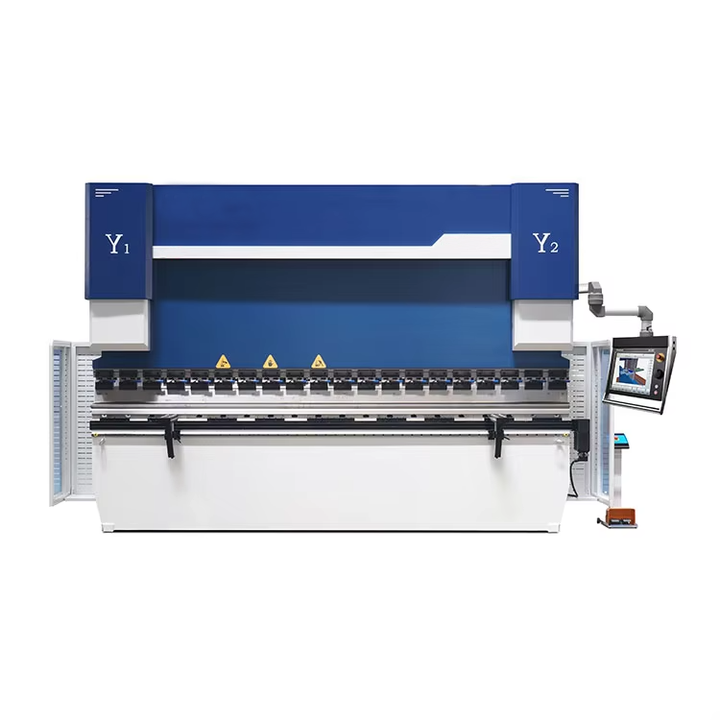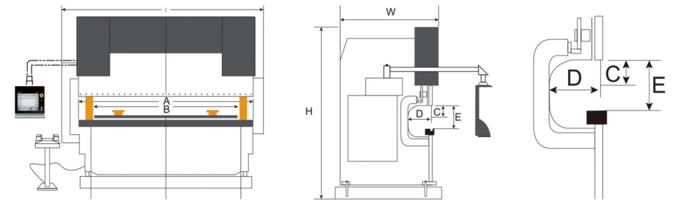
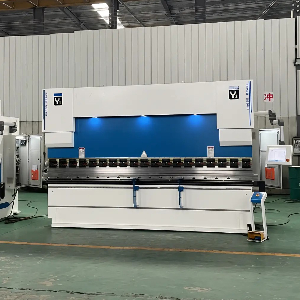
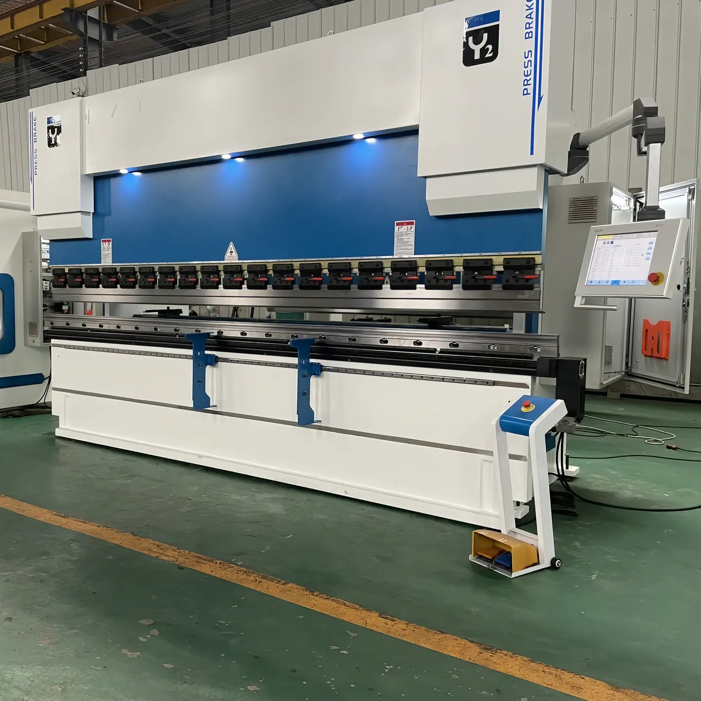
Bending Machine Description
⏺ The electro-hydraulic servo press brake machine body adopts an integral steel plate welded structure, tempered in a large tempering furnace to eliminate deformation caused by welding and processing stresses, ensuring the machine tool's precision retention.
⏺ Imported internationally renowned brand electro-hydraulic servo valves and scales constitute a precise control system. The slider position feedback is highly accurate, ensuring smooth and accurate operation, good synchronization performance, and high bending and block repeatability.
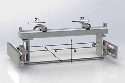
⏺ The back gauge adopts a more comprehensive 4+1 axis back gauge mechanism, 6+1 axes optional.
⏺ The hydraulic system uses an integrated control system, reducing piping installation, overcoming oil leakage, ensuring the machine tool's operational stability, and featuring a simple and aesthetically pleasing appearance.
⏺ An automatic mechanical deflection compensation mechanism eliminates the impact of slider deformation on workpiece quality;
⏺ CNC system automatically adjusts the compensation amount, making operation convenient and accurate.
⏺ The CNC system uses the American HACO 60 brand bending machine-specific CNC system.
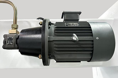
Main Motor
Equipped with a renowned brand motor
and a national standard all-copper movement
it offers low noise and a long service life.
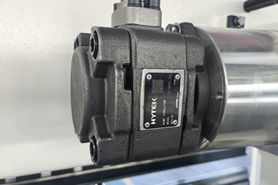
High-Pressure Oil Pump
Utilizes a Hytek (Sunny, USA) high-performance oil pump with high volumetric efficiency.
Minimal flow and pressure fluctuations, and low noise.
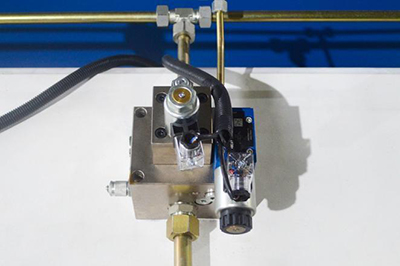
Servo valve assembly
Including Heck (USA) and Rexroth (Germany) (Germany Rexroth optional).
It utilizes the most advanced electro-hydraulic servo synchronization control system and a three-piece hydraulic system for high synchronization accuracy.
Slider Structure
The slider is rigidly connected to the cylinder. The guideway is fitted with lubricated guide plates made of wear-resistant material.
The dual-track structure and auxiliary guide wheels ensure the slider's operating accuracy, speed, and resistance to side loads.
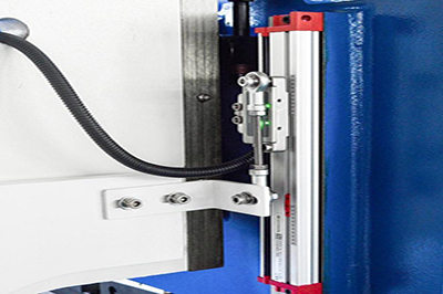
Magnetic Scale
Magnetic scales are installed at both ends of the machine tool to detect the distance between the slide and the worktable.
Position data is fed back to the CNC system, which then outputs signals to control the operation of the proportional servo valves, ensuring precise synchronization between the two cylinders.
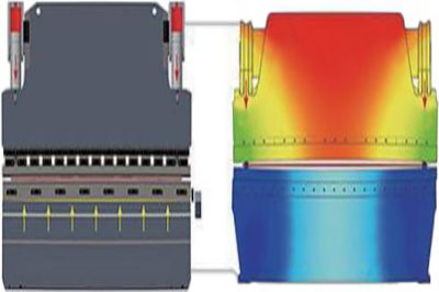
COMPENSATIONSYSTEM
The compensation system is a CNC axis that controls the amount of camming applied to the worktable, ensuring precise deflection compensation along the entire length of the worktable.
The camming worktable consists of a set of beveled gate wedges. Each wedge is designed and manufactured based on finite element analysis of the deflection curves of the slider and worktable uprights during bending.
The CNC system calculates the required compensation based on the load force during workpiece bending (which causes deflection of the slide and table support) and automatically controls the relative movement of the cam wedge, effectively compensating for the deflection of the slide and table, resulting in ideally bent workpieces.
This deflection-compensating table achieves "pre-cam" motion through position control. A set of modules creates a curve along the machine's length that matches the actual deflection, ensuring consistent feedback between the upper and lower dies during bending and consistent angles along the length of the bent workpiece.
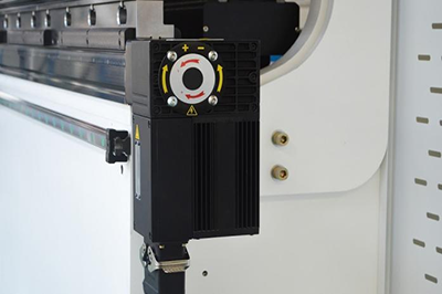
Ear positioning system
It adopts the latest design of precise and stable back gauge device, and the servo motor drives the ball screw, which has the characteristics of fast speed and high positioning accuracy.
The unique dual linear guide structure allows the finger to move left and right along the linear guide to ensure positioning accuracy. It also features a unique three-stage adjustable finger structure.
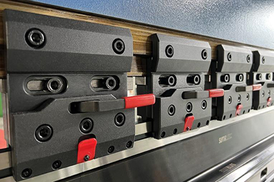
UPPERDIEQUICKCLAMP
Independently designed and produced, it features quick loading and unloading functions to improve loading and unloading efficiency and safety during replacement.
it undergoes heat treatment and quenching process to improve structural strength and wear resistance.
independent precision testing, with accuracy controlled within 0.02mm, ensures consistency in mold installation.
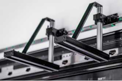
FRONTSUPPORTDEVICE
It adopts a height-adjustable support rack, a thickened chrome-plated polished rod, and a flat support that also uses a chrome-plated double-support polished rod, making it easier to adjust up and down and push the plate in.
The main polished rod can be rotated 180 degrees and is sturdy and durable.
Why was this option chosen?
•Keyboard shortcuts and touch navigation.
• 15" high-resolution true-color display with up to 8-axis control (Y1, Y2 + 6 auxiliary axes).
• Deflection compensation control.
• Simple and easy-to-use 2D graphical programming; the system automatically calculates bending processes in real-time and intuitively, allowing even beginners to quickly get started.
• Features mold library/material library/product library.
• Supports servo communication/analog control.
• Advanced Y-axis control algorithm, perfectly compatible with imported and domestic valves.
• USB peripheral interface.
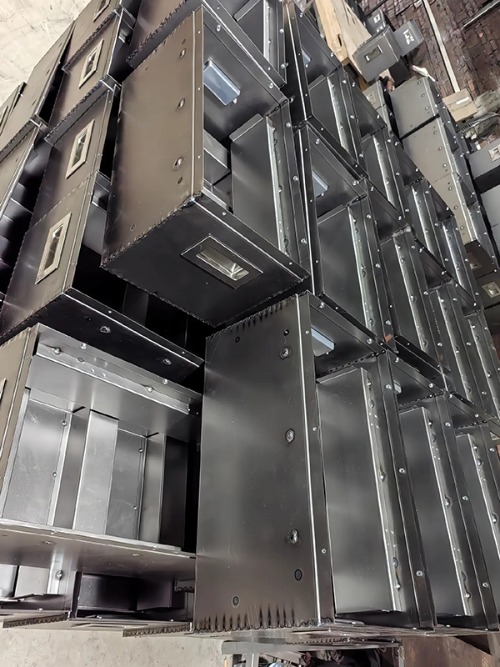
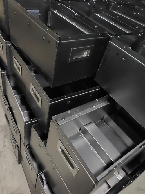
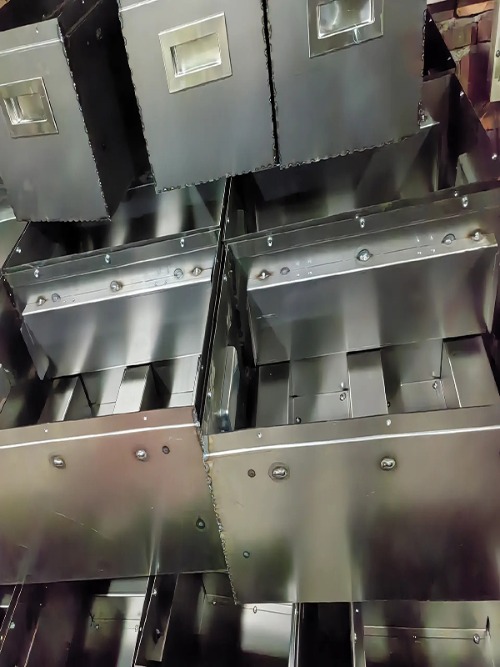
Sheet metal bending product display