Equipment display
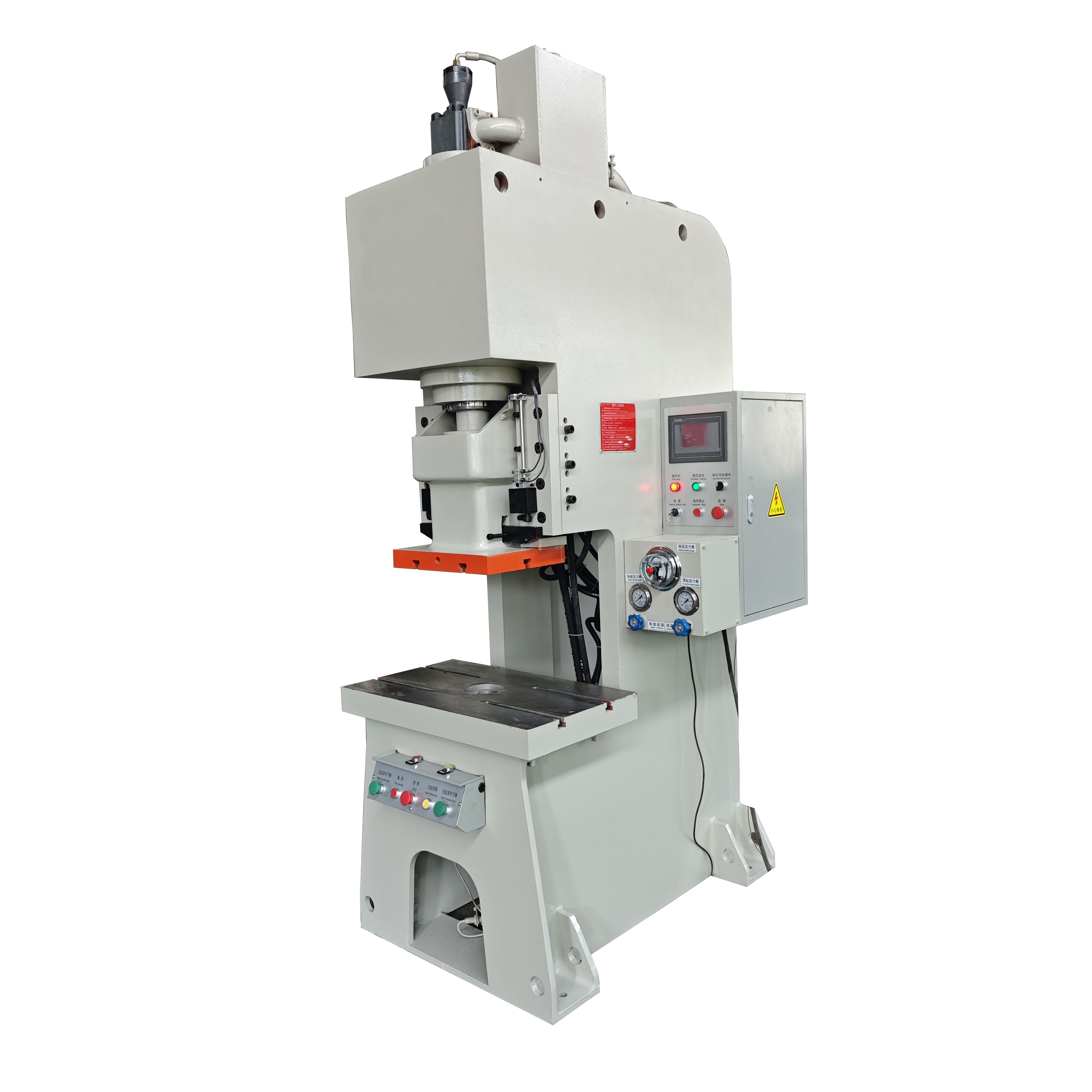
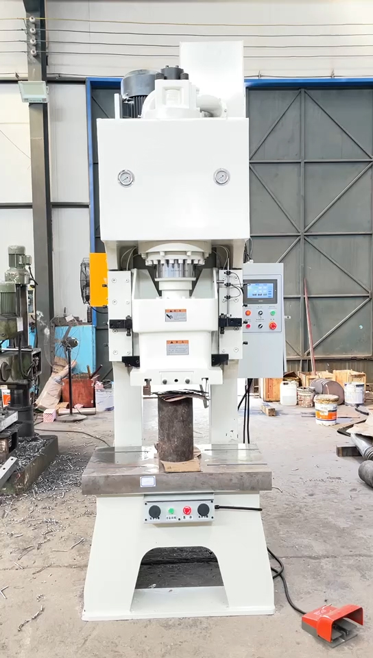
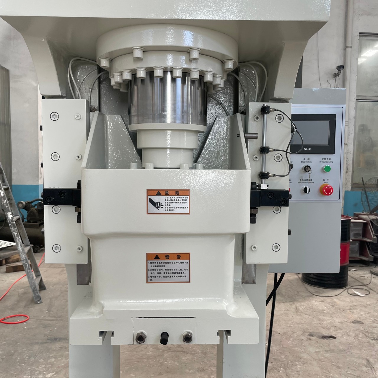
Our hydraulic press machine is designed for efficient and precise metal forming operations. Powered by a stable hydraulic system and built with a heavy-duty welded steel frame, it provides consistent pressure output, smooth operation, and excellent durability for long-term industrial use.
Compared with mechanical presses, hydraulic presses offer better control over pressure and stroke, making them ideal for complex forming processes and customized production requirements. The machine supports a wide range of applications including punching, bending, forming, deep drawing, and assembly operations.
Core Advantages
Rigid Frame Structure
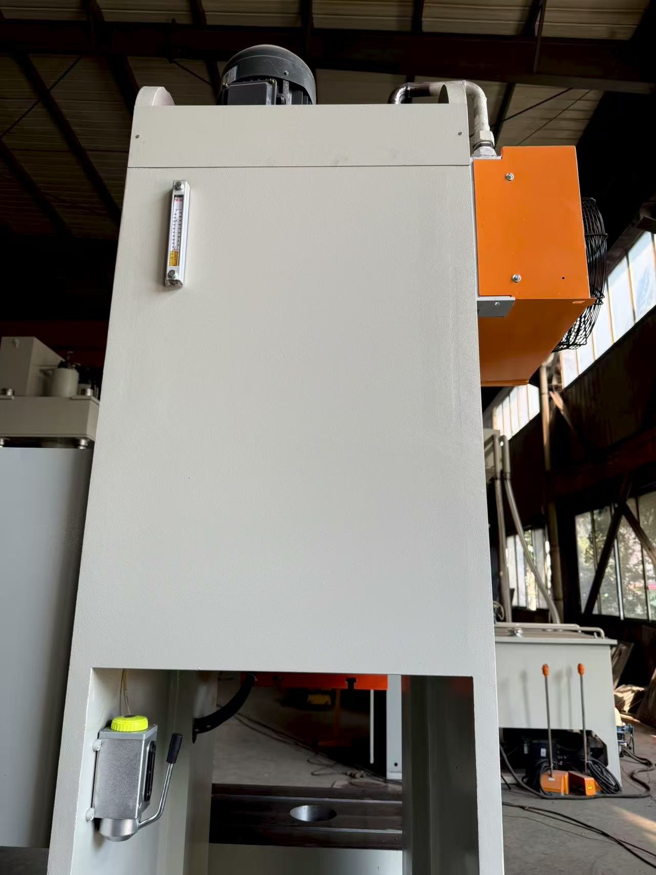
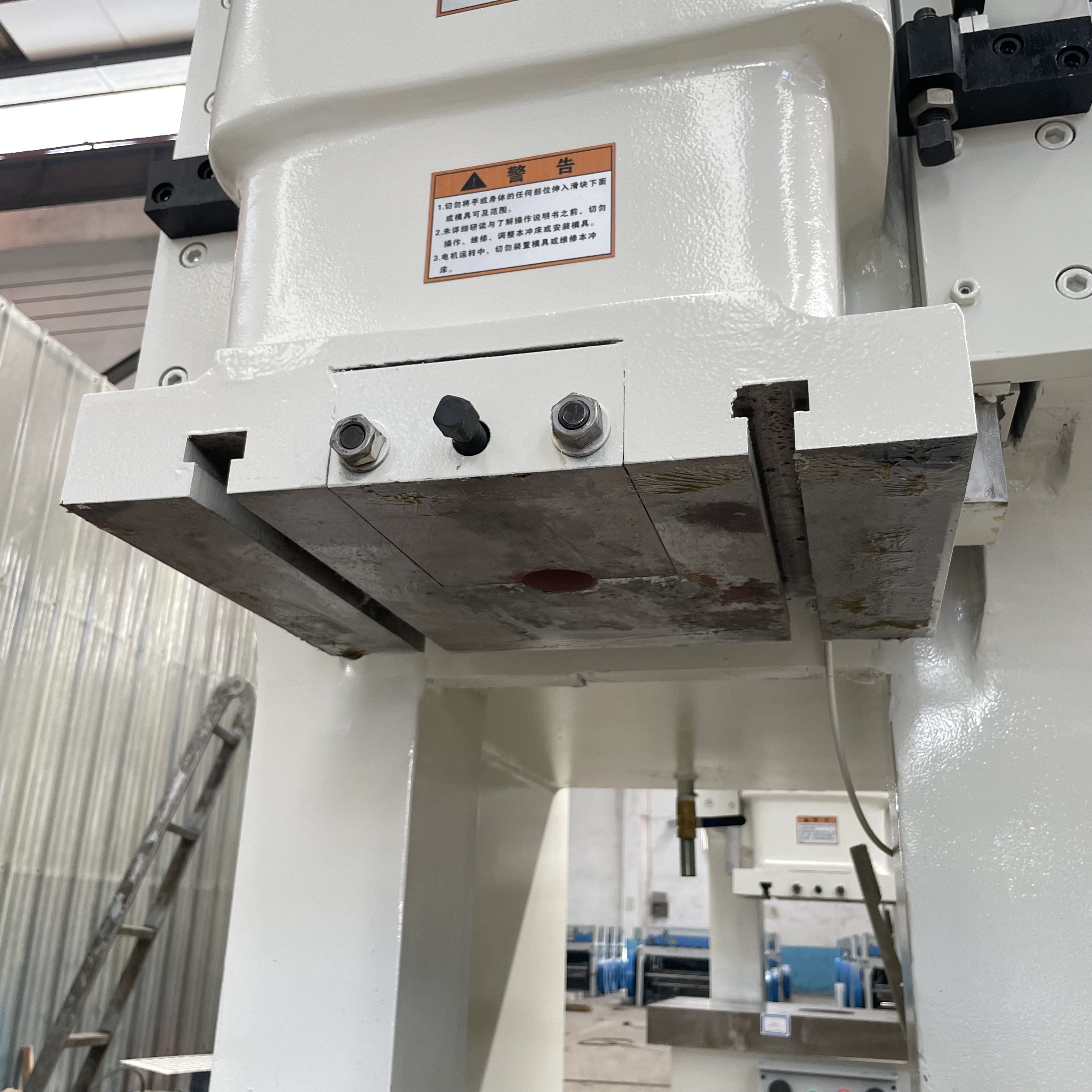
The machine frame is manufactured from high-strength steel plates with precision welding and stress-relief treatment, ensuring excellent rigidity, accuracy, and resistance to deformation.
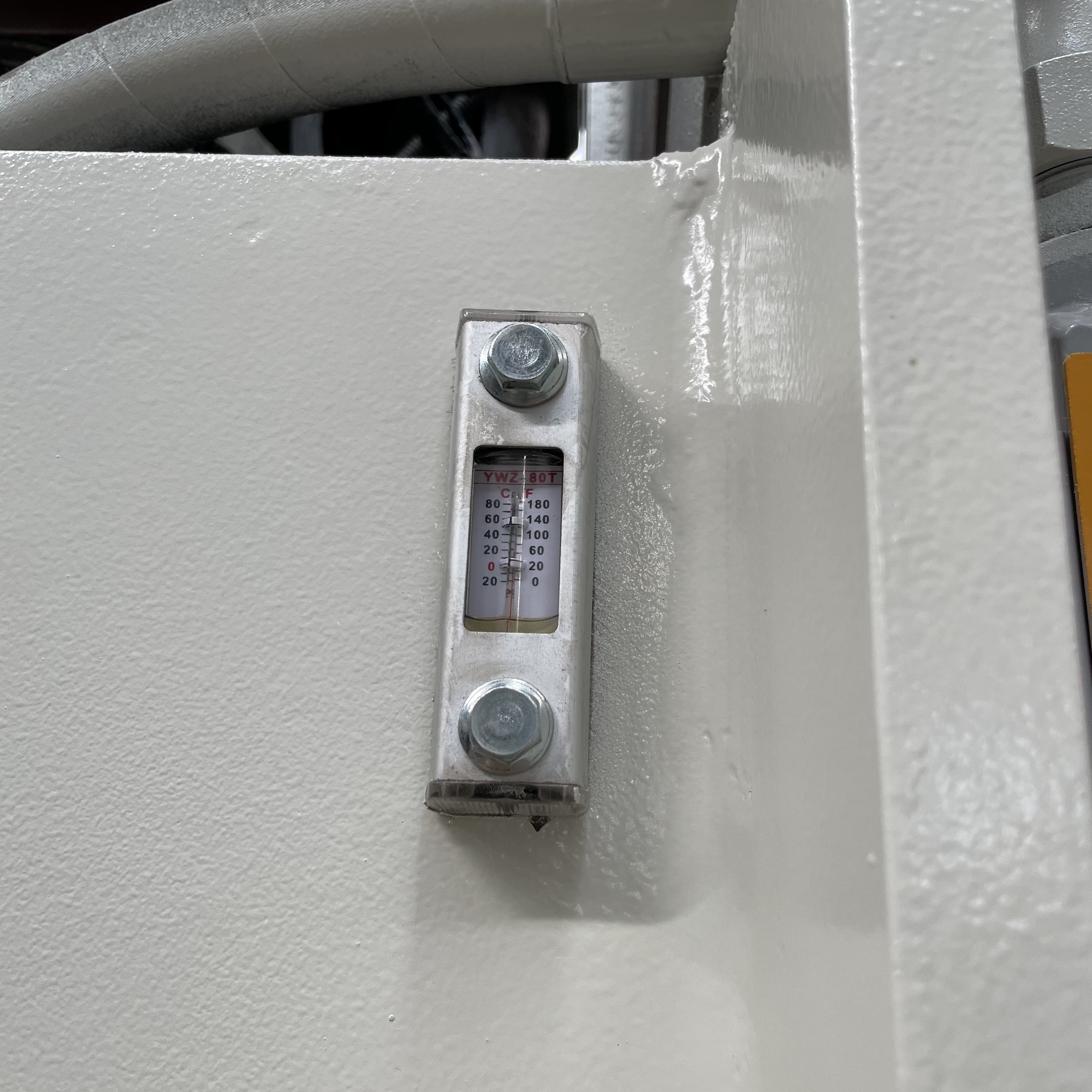
Stable Hydraulic System
Equipped with high-quality hydraulic components, the system delivers smooth pressure output, low noise, and reliable long-term performance even under continuous operation.
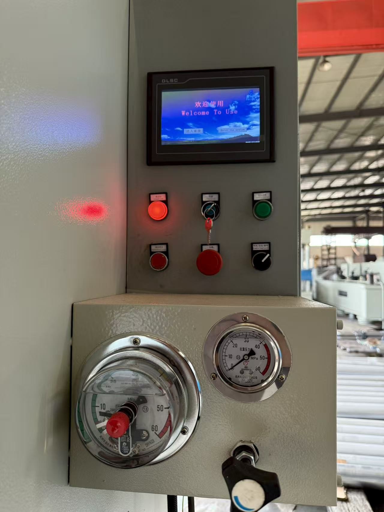
Precise Control
Pressure, stroke, and holding time can be accurately controlled. Optional PLC and touch screen systems allow easy operation and high repeatability.
Flexible Customization
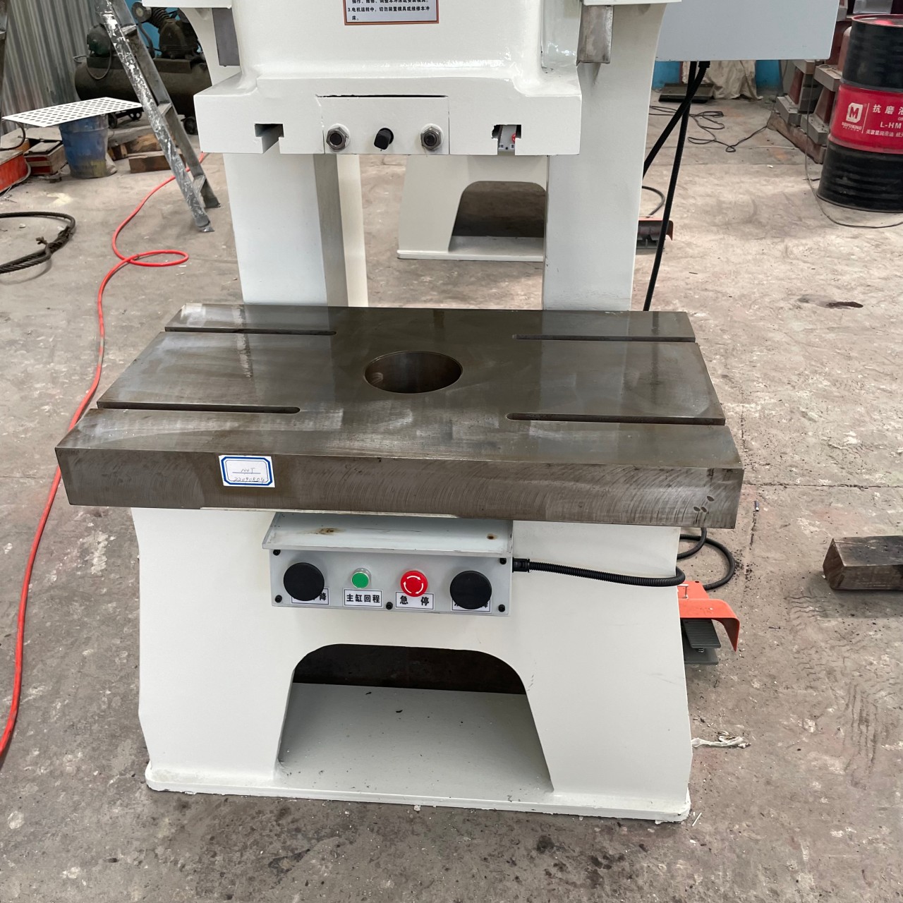
Tonnage, stroke, table size, mold installation, safety devices, and control systems can all be customized to match specific production requirements.
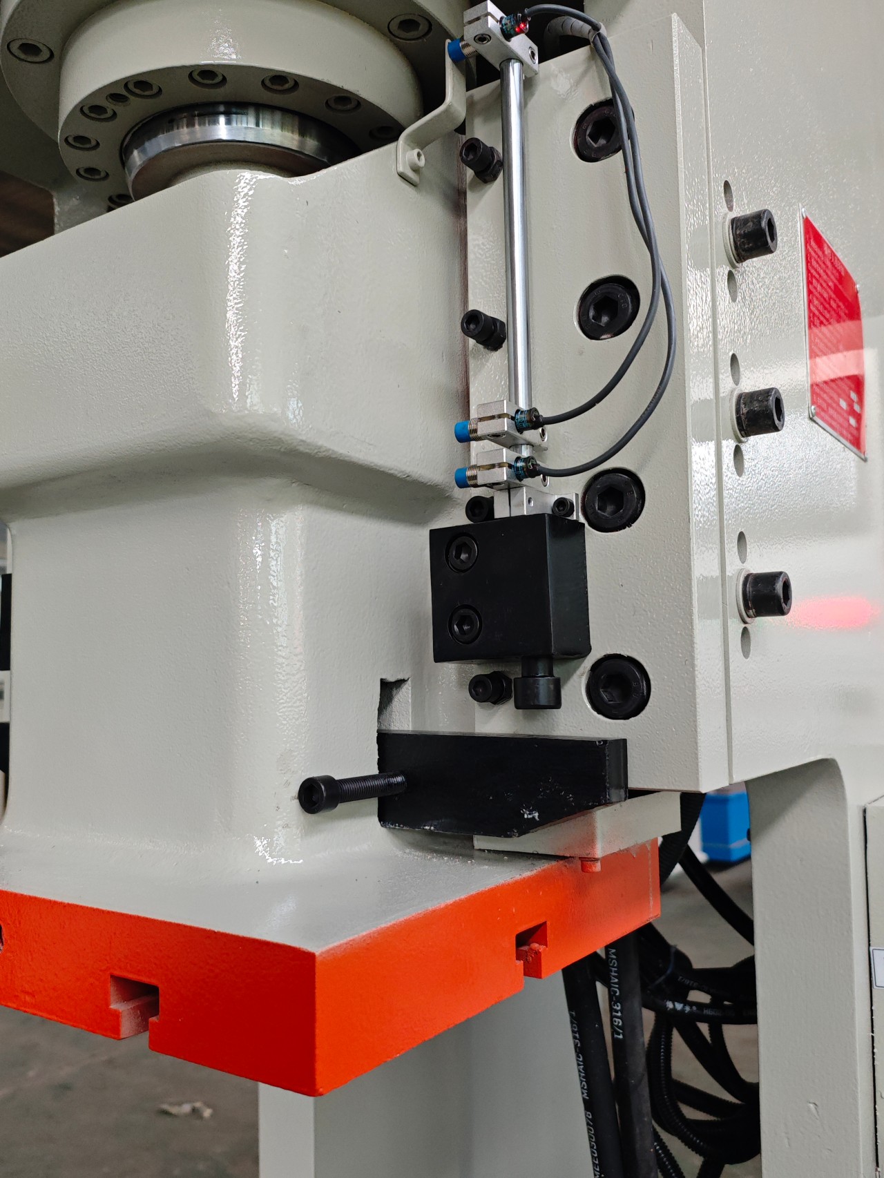
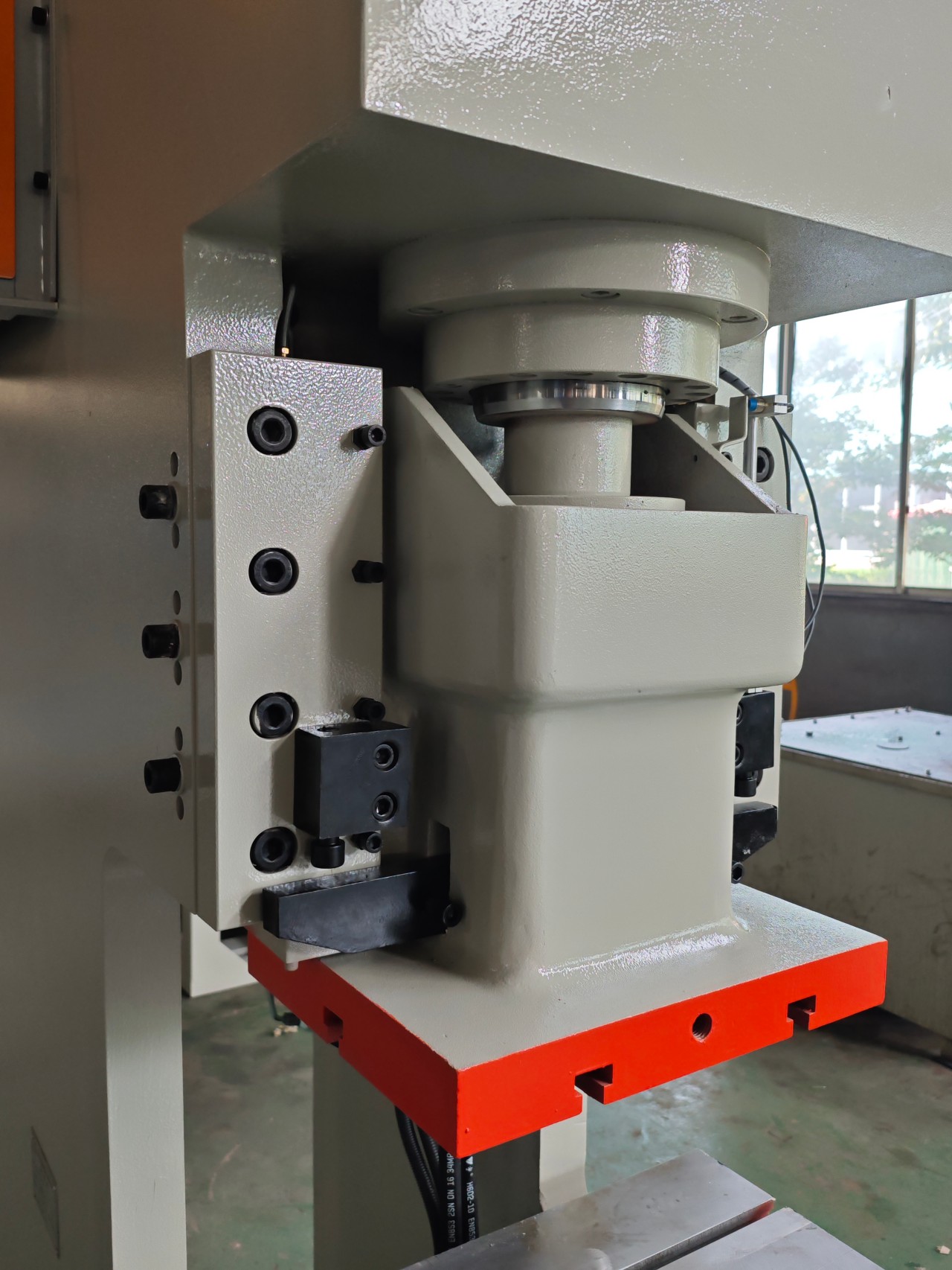
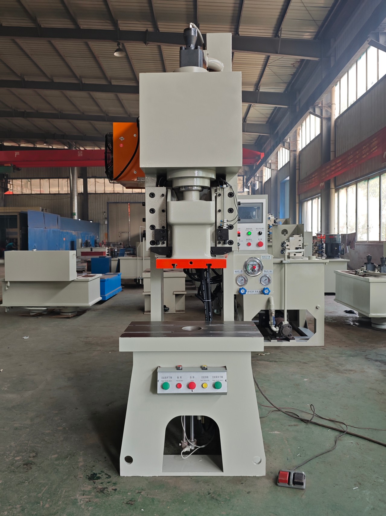
Slide/Ram: The core actuator of the punch press, supporting the upper die and moving up and down; it is the source of force.
Upper Die: Mounted at the lower end of the slide, it mates with the lower die and directly contacts the material; it is one of the stamping tools.
Die Shoe: Supports the lower die and is fixed to the press bed (frame); it is another part of the stamping tool.
Die: The combination of the upper and lower dies; it is the decisive tool for shaping a specific workpiece.
Power Transmission Mechanism: Such as a crankshaft, connecting rod (mechanical), or hydraulic cylinder (hydraulic), it converts the motor power into the linear motion of the slide.
Applications
Our hydraulic press machines are widely used in:
Sheet metal punching and forming
Bending and straightening
Deep drawing processes
Powder compacting
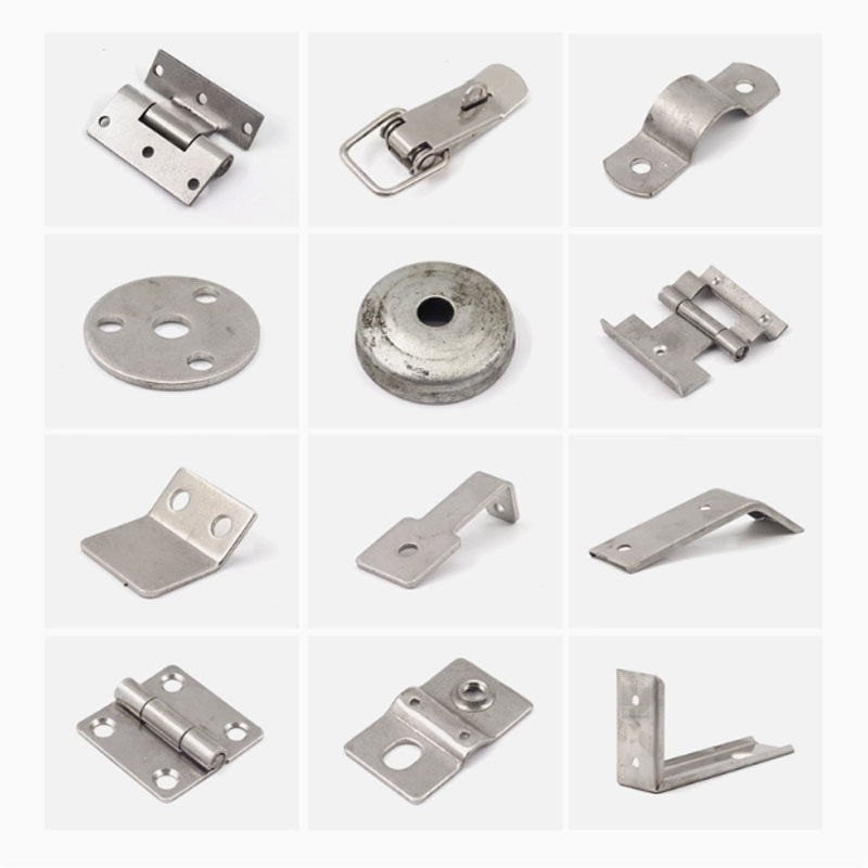
Automotive and hardware parts manufacturing
Electrical and industrial components production
Suitable materials include carbon steel, stainless steel, aluminum, copper, and other metal sheets.
Operation & Safety
Two-hand operation system
Emergency stop button
Overload protection
Optional safety light curtain
CE standard electrical configuration (optional)
Safety and ease of operation are fully considered in the machine design.
Manufacturing & Quality Control
Each hydraulic press machine is manufactured under strict quality control procedures:
Precision machining of key components
Frame welding and stress relief
Hydraulic pressure testing
Electrical system inspection
Trial operation before delivery
This ensures stable performance and consistent quality for every machine.
After-Sales Service
Warranty: 12–24 months
Online technical support
Installation and operation manuals
Video guidance for setup and maintenance
Long-term spare parts supply
We provide reliable after-sales service to support customers worldwide.
FAQ
Q1: Can the hydraulic press be customized?
A: Yes, tonnage, stroke, table size and control system can all be customized.
Q2: What materials can it process?
A: Carbon steel, stainless steel, aluminum, copper and other metal sheets.
Q3: What is the delivery time?
A: Usually 25–40 working days after deposit.
Q4: Do you provide installation support?
A: Yes, we provide manuals, videos and online guidance.